
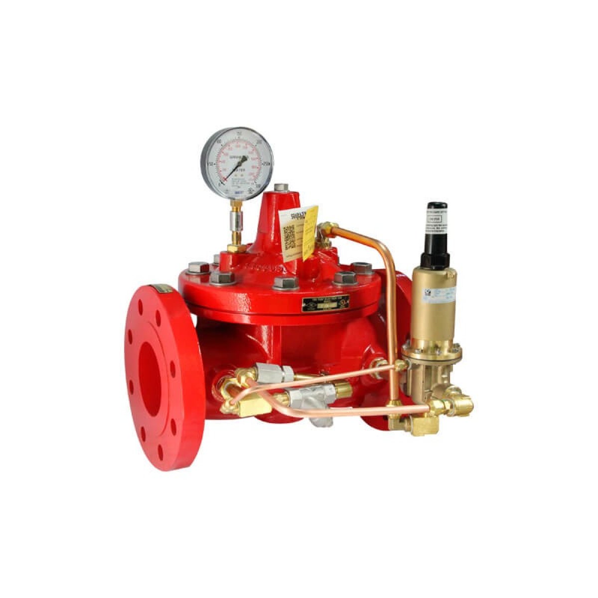
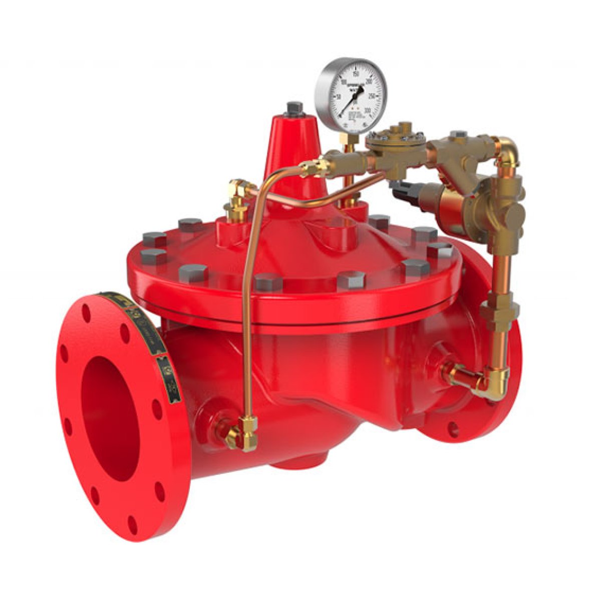
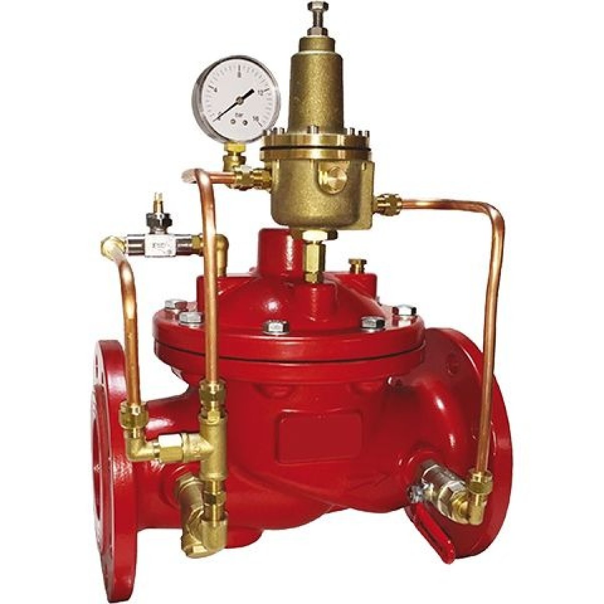
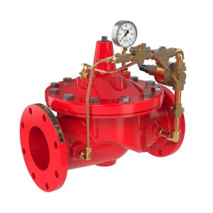
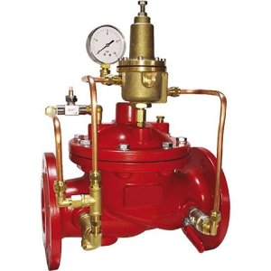
Overpressure Protection Pressure Relief Valve An industrial-grade, direct-acting spring-loaded pressure relief valve engineered to automatically safeguard piping networks, pressure vessels, and hydraulic systems against catastrophic overpressure events. Utilizing a precision-calibrated internal spring, this valve cracks open immediately when system pressure breaches a pre-determined safety threshold, safely diverting excess fluid volume to a drain or bypass loop and resealing automatically once safe baseline operating parameters are restored.
Fail-Safe Kinetic Overpressure Interception for Fluid Infrastructure
In high-pressure pumping manifolds, closed-loop thermal circuits, and municipal water transmission trunks, pressure surges are an omnipresent threat. Sudden valve closures, emergency pump stops, or thermal expansion can trigger extreme kinetic spikes (water hammer). If left unmanaged, these spikes will instantly rupture pipe joints, crush delicate instrumentation, and cause catastrophic structural blowouts. The Pressure Relief Valve (PRV) serves as the ultimate mechanical insurance policy, providing a dedicated, autonomous release path that limits system pressure to a designated safety envelope.
The valve functions entirely via mechanical force balance. Inside the valve chamber, an internal compression spring exerts a continuous downward force on a sealing disc, holding it tightly locked against the valve seat. Under standard operational conditions, the process fluid's upward pressure is lower than the spring's preset mechanical tension.
However, the moment system pressure rises above the setpoint, the fluid overcomes the spring force and lifts the disc off its seat. This instantly opens a large discharge path, allowing excess volume to vent cleanly away from the primary loop. As the line pressure drops back down to safe levels, the spring expands, forcing the disc back onto the seat to achieve a bubble-tight seal before unnecessary fluid is wasted.
Key Performance Features
Precision Factory-Calibrated Spring Matrix: Outfitted with an industrial-grade, fatigue-resistant alloy steel spring that can be fine-tuned via an external adjusting bolt to match exact project design pressure requirements.
Rapid Response Linear Discharge: Designed with a high-lift disc mechanism that breaks open instantly to maximize volumetric fluid discharge, minimizing the duration of dangerous overpressure states.
Resilient vs. Metal-to-Metal Sealing Options: Available with premium Viton/EPDM encapsulated discs for bubble-tight gas and liquid sealing, or precision-lapped stainless steel seats for high-temperature chemical processing configurations.
Angled Body Configuration: Features a standard $90^{\circ}\text{ angled inlet-to-outlet interface Layout}$, allowing the valve to serve as a neat structural corner turn directly into a dedicated drain or reservoir return manifold.
Anti-Corrosive External and Internal Coatings: The heavy ductile iron body is fully encapsulated inside and out with an electrostatically applied fusion-bonded epoxy (FBE) finish, protecting the system against scaling and aggressive environmental chemistry.
Tamper-Proof Mechanical Cap Safeguard: The top adjusting stem is shielded by a heavy threaded cap or sealed wire-lock array, preventing unauthorized or accidental field adjustments to the safety setpoint.
Ideal Infrastructure Applications
Fire Pump House Discharge Loops: Installed on the main output manifold of high-torque electric or diesel fire pumps to vent excess churn pressure when system control valves are closed.
Boiler Plant Rooms & Thermal Systems: Providing mandatory code-compliant thermal expansion overpressure protection for closed-loop heating lines and pressure vessels.
Chilled Water Piping Networks: Protecting long vertical HVAC distribution risers in high-rise towers against sudden hydraulic column shifts and pressure spikes.
Technical Performance MatrixEngineering MetricThreaded Utility Relief ValveFlanged Heavy-Duty Relief ValveNominal Diameter Range$1/2"\text{ up to }2"\text{ (Threaded)}$DN50 ($2"$) up to DN300 ($12"$)End Connection InterfaceMale/Female NPT or BSP ThreadedFlanged (ANSI Class 150/300 / PN16 / PN25)Valve Body Pattern$90^{\circ}\text{ Angled Inlet/Outlet Geometry}$$90^{\circ}\text{ Angled Inlet/Outlet Geometry}$Set Pressure Range2.0 bar to 16.0 bar ($30\text{ to }232\text{ PSI}$)3.5 bar to 24.1 bar ($50\text{ to }350\text{ PSI}$)Fluid Temperature Limits$-10^{\circ}\text{C}$ to $+90^{\circ}\text{C}$ (EPDM Seated)$-20^{\circ}\text{C}$ to $+200^{\circ}\text{C}$ (Metal Seated)Main Body MetallurgyForged Brass / Cast Stainless SteelDuctile Iron (ASTM A536) / Cast Carbon SteelSpring & Trim MetallurgyHigh-Tensile Stainless Steel (AISI 302/316)Chrome Vanadium Alloy Steel / Grade 304 SSStandard Procurement Package Components
Complete Pressure Relief Valve Assembly with Calibrated Spring
Factory Sealed Protective Top Cap with Tamper-Evident Lead Wire Seal
Pre-cut Flange Gaskets and Heavy-Duty Installation Bolt Hardware (For Flanged Models)
Official Certified Factory Hydrostatic Shell Test and Pressure Calibration Certificate
Optional System Add-ons: Visual Pressure Gauges, Exhaust Waste Cone Spools, and Lift Levers for Manual Operational Verification Testing (Sold Separately)