
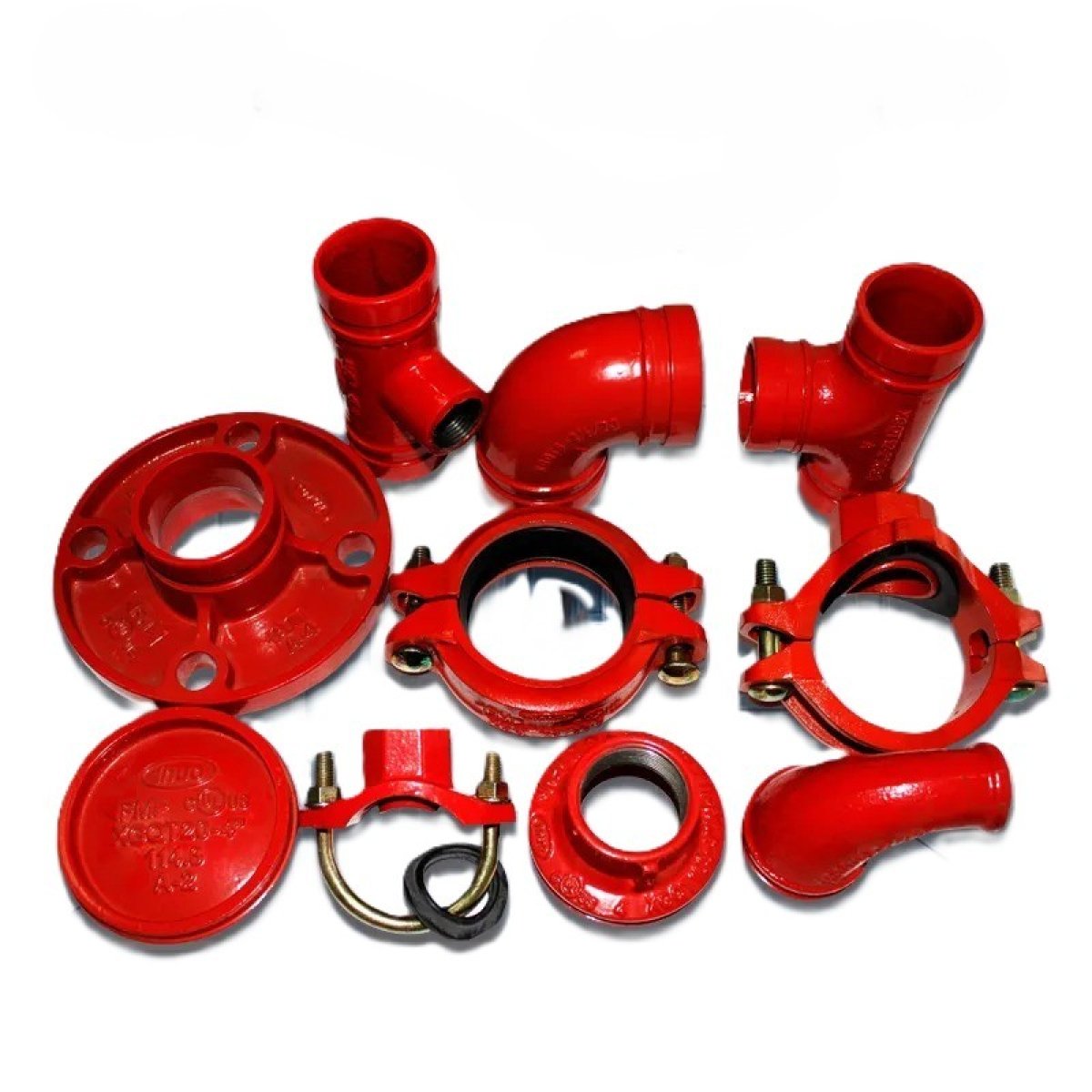
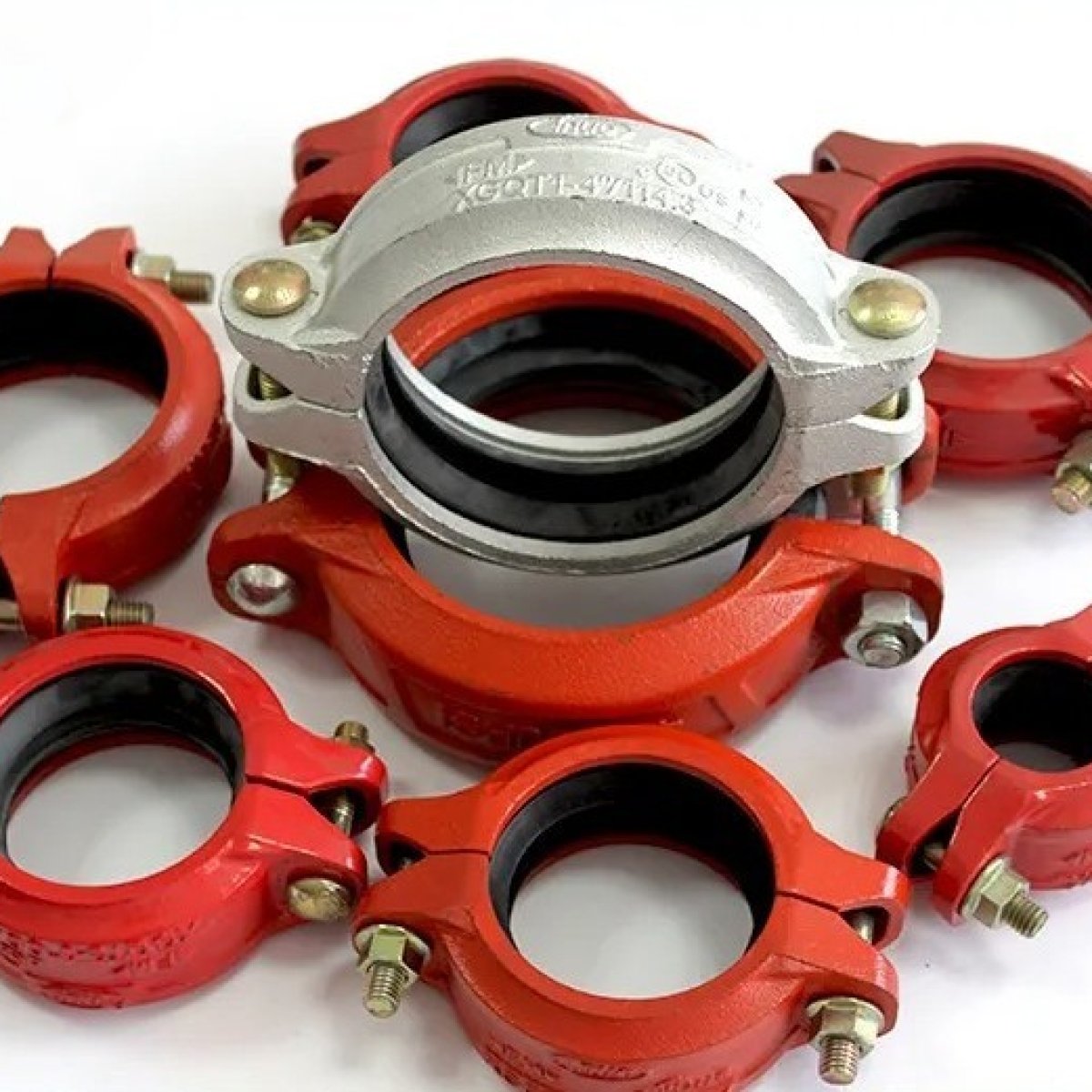
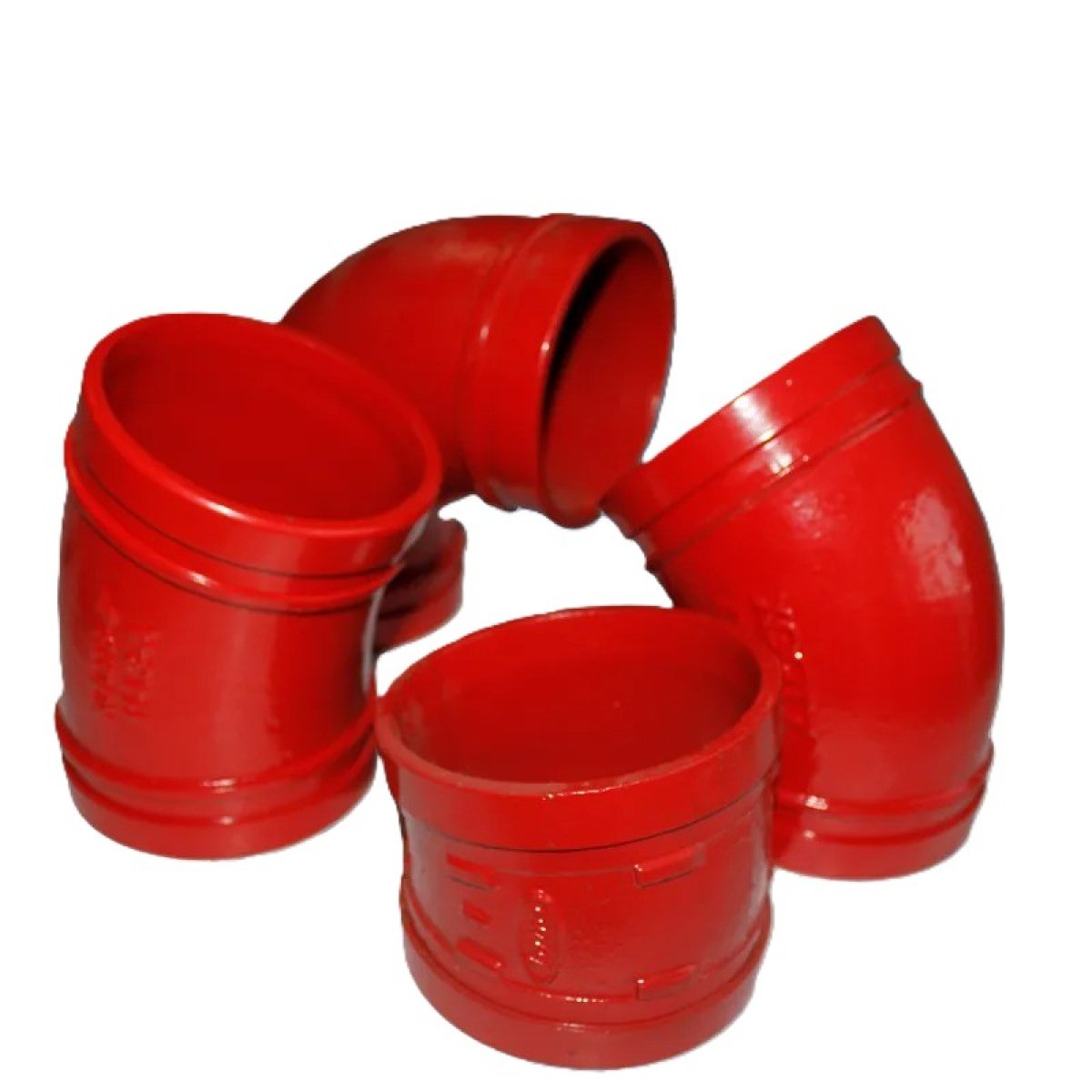
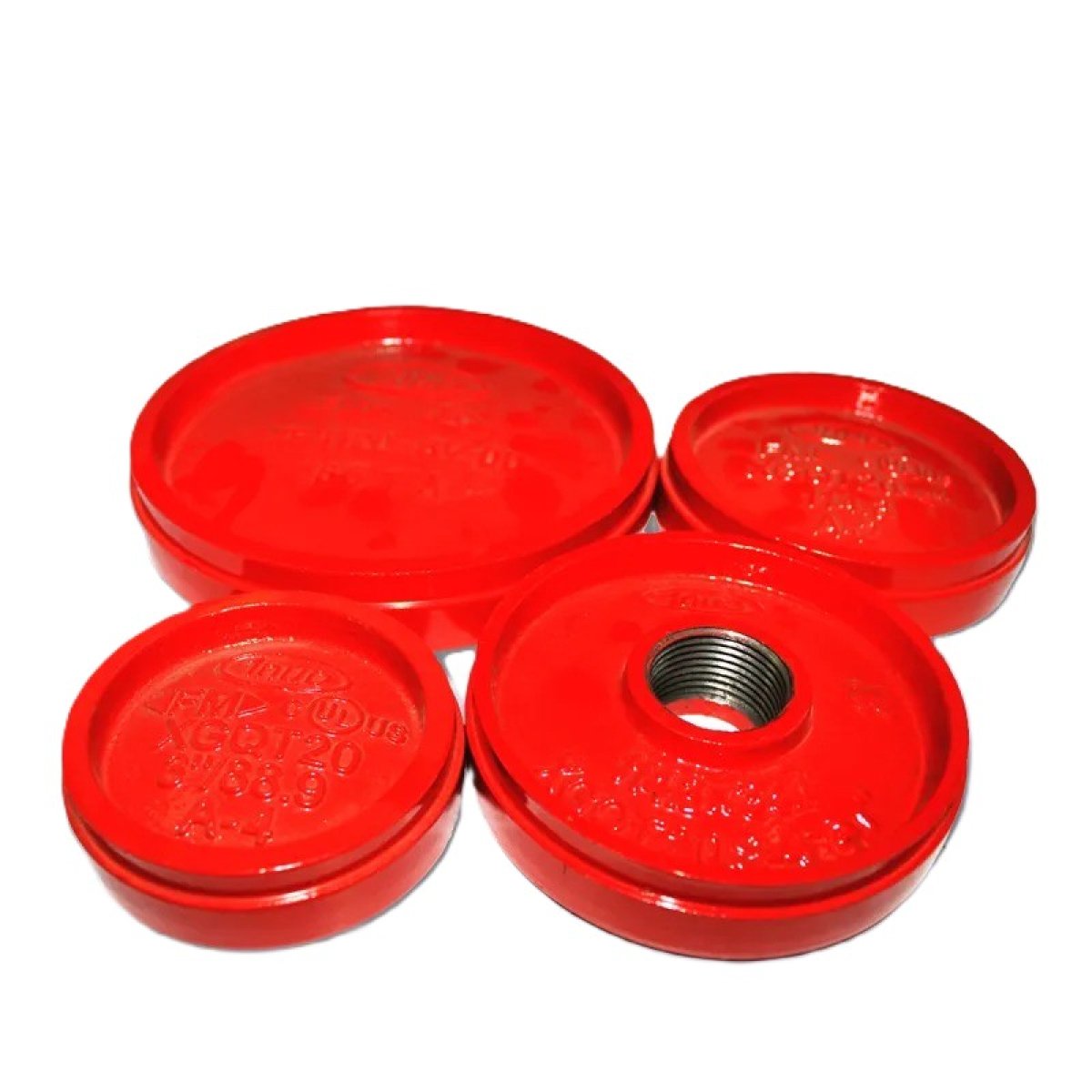
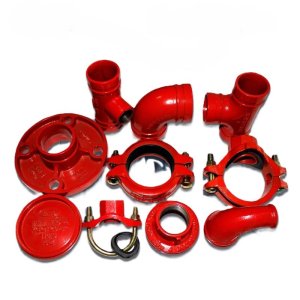
High-Pressure Piping Components (Elbows, Tees, Reducers, Flanges) An enterprise-tier suite of structural fluid-routing components engineered to direct, branch, adapt, and securely interconnect high-pressure piping networks. Manufactured from heavy-duty ductile iron, carbon steel, or forged stainless steel, these components feature precision-engineered flow paths and diverse connection end-types (grooved, threaded, or flanged) to guarantee leak-proof fluid transmission across commercial, municipal, and industrial infrastructure systems.
The Structural Backbone of Complex Fluid Distribution Architecture
While straight pipe lengths handle the bulk distance of a water transmission network, plant room, or fire suppression grid, they cannot navigate physical obstacles, branch into sub-networks, adapt to changing pipe sizes, or interface with machinery. Pipe Fittings are the essential geometric building blocks that transform individual conduits into a cohesive, high-performance fluid distribution system.
Our structural fittings are manufactured using precision casting, forging, and machining processes that eliminate micro-porosity and internal stress points. They are engineered to handle intense hydraulic friction, structural expansion, and sudden pressure drops without fracturing or weeping. Available in a wide variety of connection types—including rapid-install grooved ends (AWWA C606), traditional national taper threads, and high-strength bolt-up flanges—these fittings ensure complete network flexibility and structural integrity.
Core Geometric Profiles and Functions
An engineered piping infrastructure relies on four fundamental fitting geometries to control fluid paths:
1. Elbows ($90^{\circ}$ and $45^{\circ}$)
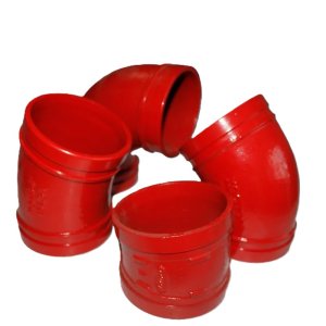
The Directional Pivot: Navigates structural columns, walls, and grade shifts. Available in Long Radius (LR) configurations ($1.5\times\text{ the nominal pipe diameter}$) to reduce internal fluid friction and minimize wear from high-velocity sand or grit, or Short Radius (SR) profiles for tight mechanical rooms.
2. Equal and Reducing Tees
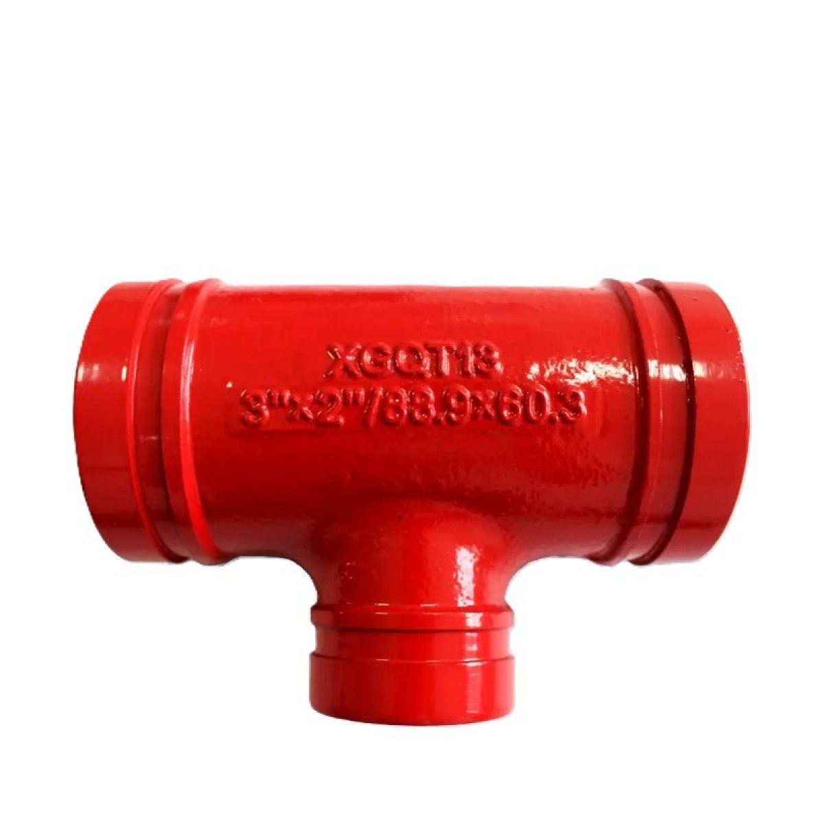
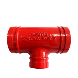
The Network Branch: Creates a $90^{\circ}$ branch line out from the primary header line. Equal Tees maintain uniform diameters across all runs, while Reducing Tees feature a smaller branch port to feed sub-distribution loops without installing separate reduction joints.
3. Reducers (Concentric vs. Eccentric)
The Velocity Adapter: Safely bridges two pipes of different nominal diameters.
Concentric Reducers: Feature a symmetrical, cone-shaped design to maintain a shared centerline. They are ideal for vertical piping segments.
Eccentric Reducers: Feature one flat edge aligned with the top or bottom of the pipe run. This design prevents hazardous air pockets from forming in horizontal lines, making them mandatory for fire pump suction inlets.
4. Flanges (Weld-Neck, Slip-On, Blind)
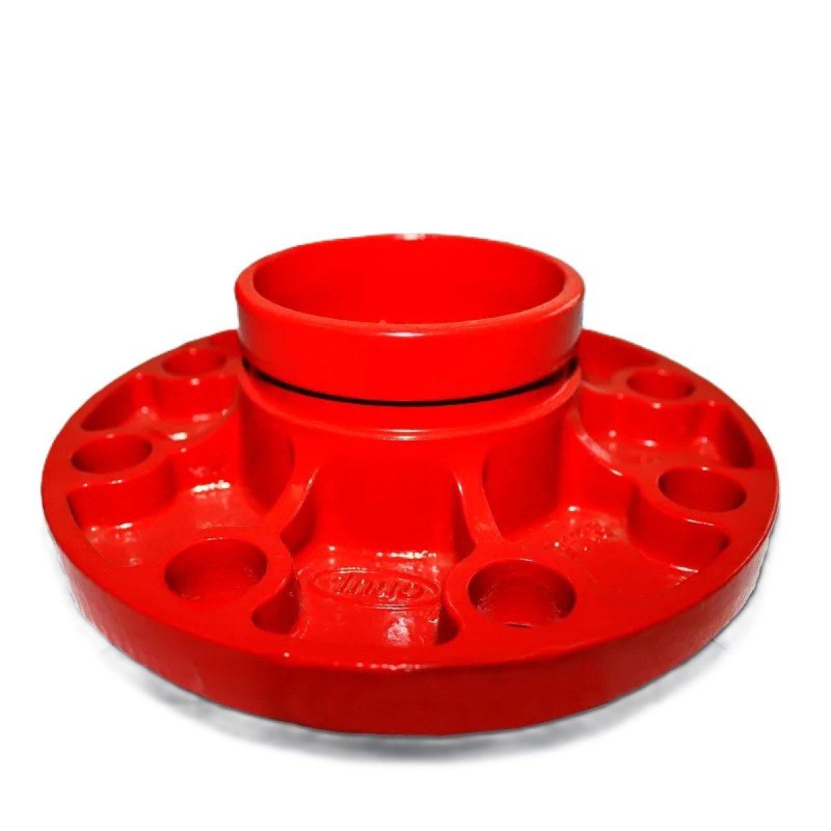
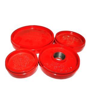
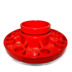
The Mechanical Interconnect: Provides a heavy-duty, bolt-together transition point between pipes, valves, pumps, and tanks, allowing sections of the system to be dismantled for maintenance. Blind Flanges are solid discs used to seal off the terminal ends of piping lines for pressure testing or expansion routing.
Key Performance Features
Anti-Corrosive Fusion-Bonded Epoxy (FBE): Ductile iron components are fully coated inside and out with an electrostatically applied epoxy shield, protecting the underlying metallurgy from aggressive soils, mineral scaling, and internal rusting.
Hydrodynamic Interior Geometry: Engineered with smooth internal radius profiles that reduce fluid turbulence, minimizing system pressure drops and optimizing total pump energy efficiency.
Precision-Machined Grooved Interfaces: Grooved variants feature factory-cut radius dimensions that accept standard mechanical split-couplings, cutting installation labor times by up to 75% compared to traditional on-site flange welding.
Strict Quality and Safety Standards: Built and fully tested in compliance with global engineering protocols, including ASME B16.9 (for steel butt-welding fittings), AWWA C110 (for ductile iron fittings), and UL/FM safety guidelines for fire infrastructure.
Ideal Infrastructure Applications
HVAC Chiller Rooms & Plant Loops: Managing heavy-diameter, continuous fluid turns and equipment isolation joints.
NFPA-Compliant Fire Protection Mains: Constructing robust vertical riser grids, pump manifolds, and multi-zone distribution pipelines.
Municipal Water Infrastructure: Interconnecting high-volume underground mainlines, pressure-reducing stations, and treatment plant networks.
Technical Performance MatrixFitting AttributeDuctile Iron Grooved SystemForged Carbon Steel SystemStainless Steel SystemNominal Size RangeDN25 ($1"$) up to DN600 ($24"$)DN15 ($1/2"$) up to DN1200 ($48"$)DN15 ($1/2"$) up to DN300 ($12"$)Material ProtocolASTM A536 Grade 65-45-12ASTM A234 WPB / A105 ForgedASTM A403 WP304 / WP316LConnection EndsRigid/Flexible Grooved JointsButt-Weld / Socket-Weld / FlangedThreaded (NPT/BSP) / Weld EndMax Working PressureUp to 20.7 bar (300 PSI)Class 150 / 300 / 600 / 3000Sch 10S / 40S / 80S Pressure SpecsFactory Shell TestingHydrostatic up to 2.0$\times$ WorkingValidated via Non-Destructive Testing100% X-Ray / Dye Penetrant CheckedExternal Finish WrapRAL 3000 Red FBE / Galv CoatingBlack Primer / Rust-Inhibitor OilPickled and Passivated Natural SteelStandard Procurement Package Components
Complete Ordered Fitting Unit (Elbow, Tee, Reducer, or Flange Ring)
Material Traceability Heat-Number Documentation
Quality Assurance Alignment and Pressure Rating Certification Sheets
Required for Field Assembly: Mechanical Grooved Couplings, High-Tensile Bolt Sets, and EPDM Flange Gasket Rings (Sold Separately based on design isometric configurations)